| Previous Post | Top | Next Post |
TOC
This is my manual for TTL-232R-5V based ISP which I made several years ago. I moved this content from other place to make it easy to find. I still use this as my back up IPS. This is 5V only programmer.
I now use my Modified AVRISP MKII (in Japanese) as my main programmer. (If I every program AVR again.)
Circuit
It’s a bit un-intuitive, but USB to TTL level RS-232 adapter (Serial adapter) can be used in a special bit-bang mode. AVRDUDE supports this:
I am talking specifically the original TTL-232R-5V found in these pages:
- http://www.ftdichip.com/Products/Cables/USBTTLSerial.htm
- http://www.ftdichip.com/Support/Documents/DataSheets/Cables/DS_TTL-232R_CABLES.pdf
Connections are:
 TTL-232R-5V       ICPS connector
 GND 1 Black  -->  GND   (6 pin)
 CTS 2 Brown  -->  MOSI  (4 pin)
 VCC 3 Red    -->  VCC   (2 pin)
 TXD 4 Orange -->  RESET (5 pin)
 RXD 5 Yellow -->  SCK   (3 pin)
 RTS 6 Green  -->  MISO  (1 pin)
Here, ICPS connector is the one used by Arduino Uno. The standard AVRISP MKII cable support it.
Except for VCC and GND, you can connect any pairs as long as the
following setting in the default /etc/avrdude.conf is adjusted via
~/.avrduderc. (Yes, AVRDUDE supports this now without patch.)
programmer
  id    = "ttl232r";
  desc  = "FTDI TTL232R-5V with ICSP adapter";
  type  = "ftdi_syncbb";
  connection_type = usb;
  miso  = 2; # rts
  sck   = 1; # rxd
  mosi  = 3; # cts
  reset = 0; # txd
Invoke avrdude, e.g., for atmega32u4 as:
$ sudo avrdude -v -p atmega32u4 -c "$ISP" -Pusb ...
You can use double raw pin header as a converter.
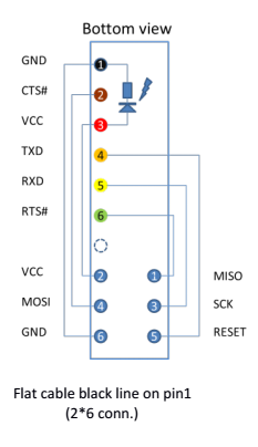
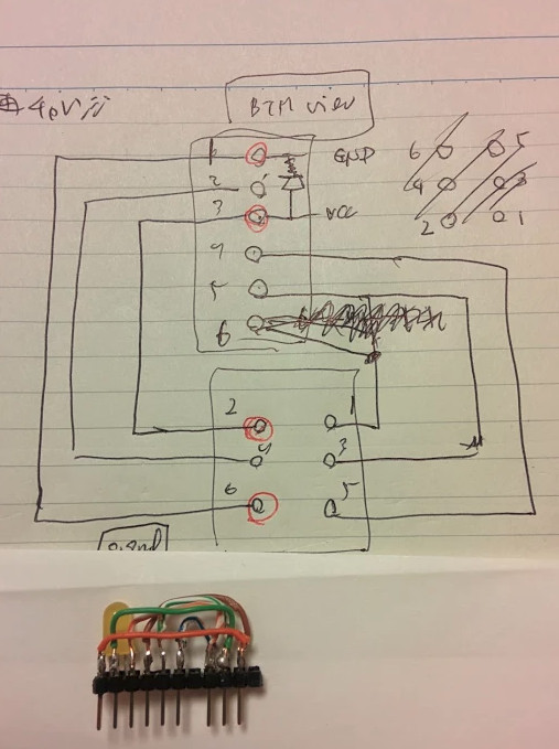
Adapter PIN Top view (connect to flat cable or clip wires)
                          TTL-232R-5V        ICPS connector
                      *   GND 1 Black   -->  GND   (6 pin)
           LED        *   CTS 2 Brown   -->  MOSI  (4 pin)
           (*)        *   VCC 3 Red     -->  VCC   (2 pin) 5V only
                      *   TXD 4 Orange  -->  RESET (5 pin)
                      *   RXD 5 Yello   -->  SCK   (3 pin)
                      *   RTS 6 Green   -->  MISO  (1 pin)
                        #################### TAPE (RED LINE)
YELLOW  2 - VCC    *  *   1 - MISO   RED
BLACK   4 - MOSI   *  *   3 - SCK    GREEN
BLUE    6 - GND    *  *   5 - RESET  WHITE (w/yellow)
                        -------------------- TAPE
Wiring to program AVR chips with FT-232RL on TTL-232R
| FT232RL | BB | TTL-232R | ICPS |
|---|---|---|---|
| TXD 1 | D0 | 4 ORANGE | 5 RESET |
| RXD 5 | D1 | 5 YELLOW | 3 SCK |
| RTS# 3 | D2 | 6 GREEN | 1 MISO |
| CTS# 11 | D3 | 2 BROWN | 4 MOSI |
| DTR# 2 | D4 | — | |
| DSR# 9 | D5 | — | |
| DCD# 10 | D6 | — | |
| RI# 6 | D7 | — | |
| VCC | – | 3 RED | 2 VCC |
| GND | – | 1 BLACK | 6 GND |
- FT232RL: IC chip in TTL-232R, D/D, Uncompatino
- BB: Bit-bang data bit
- TTL-232R: USB to TTL level RS232C converter adapter
- ICPS: ISP Connector on Arduino boards
Wiring to program AVR chips with FT232RL on old-Arduinos
| FT232RL | BB | D/D | Uncompatino | ATmega328 |
|---|---|---|---|---|
| TXD 1 | D0 | (2 ATmega) | — | |
| RXD 5 | D1 | (3 ATmega) | — | |
| RTS# 3 | D2 | — | — | |
| CTS# 11 | D3 | X3-1 | : | 18 MISO |
| DTR# 2 | D4 | — | — | |
| DSR# 9 | D5 | X3-2 | : | 19 SCK |
| DCD# 10 | D6 | X3-3 | : | 17 MOSI |
| RI# 6 | D7 | X3-4 | : | 1 RESET |
| VCC | – | VCC (com.) | VCC | |
| GND | – | GND (com.) | GND |
- D/D: Diecimila/Duemilnove pin outs for FT232RL
- Uncompatino: Cheap D/D Alternative with different PCB with short pins
| Previous Post | Top | Next Post |